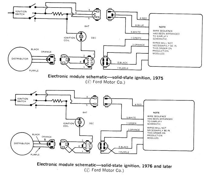
Schematic Diagram For Opel Ignition With A 7 Pin Module - Ignition Coil Checking Measuring Faults Hella : Pin 4 green live feed (battery +) pin 5 brown not connected.
Schematic Diagram For Opel Ignition With A 7 Pin Module - Ignition Coil Checking Measuring Faults Hella : Pin 4 green live feed (battery +) pin 5 brown not connected.. Pin 6 red supplementary feed (ignition) pin 7 black earth. Count the number of terminals on both ends of the module and follow the corresponding diagram. Advance control signal is a white wire pin e goes to ampseal pin #12; Symptoms of a bad ignition control module to make this short, sweet, and to the point; On a particular vehicle, consult the ignition system wiring diagram for the vehicle.
Also ecm has new capacitors in it. Lt1 power module wiring diagram and insructions thank you for purchasing our product. Count the number of terminals on both ends of the module and follow the corresponding diagram. Pin 6 red supplementary feed (ignition) pin 7 black earth. Placement of the module varies from model to model so check the appropiate service manual of your vehicle for the.
Diagram 76 Ford Ltd Ignition Wiring Diagram Full Version Hd Quality Wiring Diagram from schematron.org Placement of the module varies from model to model so check the appropiate service manual of your vehicle for the. The 7 pin hei module. Chrysler wiring diagrams are designed to provide information regarding the vehicles wiring content. A nema 4 enclosure is recommended for the ignition module. What's new for the medium duty c series •a component locator page has been included to show the location of major electronic modules on the truck. A longer pulse width means a more delayed, 'retarded' spark, while a shorter pulse width means an earlier 'advanced' spark. Also ecm has new capacitors in it. In 1862, a german entrepreneur adam opel founded an industrial company that got his name, which initially occupied.
Advance control signal is a white wire pin e goes to ampseal pin #12;
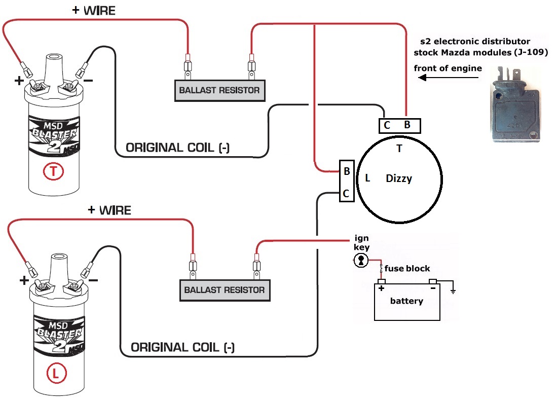
All switches, components, and modules are shown in the at rest position with the doors closed and the key removed from the ignition. Gm opel coilpack == gm 4cyl wasted spark ignition amplifier pinout. 7 pin trailer plug wiring diagram. Nfc and mst modules that are responsible for contactless payment functions using a smart phone as a credit card. Wiring diagram of 7 pin ignition module manufactured by bosch. To fit opel kadett 140 and astra,monza 180i,200i,ie,is. Placement of the module varies from model to model so check the appropiate service manual of your vehicle for the. In 1862, a german entrepreneur adam opel founded an industrial company that got his name, which initially occupied. Count the number of terminals on both ends of the module and follow the corresponding diagram. Pin 2 blue, supplementary feed (ignition) pin 3 white, earth. Please verify pin locations in these diagrams carefully and if they are incorrect email me at pmcmahon@nethere.net ability to use a digital meter is a must. As with every other rule, there is an exception. Get pin code from dump file.
The gm 7 /8 pin modules have been used in a wide variety of gm engines from 4 cylinder. 7 pin trailer plug wiring diagram. Сервера frontera 2.2 литра с двигателем x22xe. Sometimes enough to start it and it dies. As with every other rule, there is an exception.
Diagram Voice Coil Wiring Diagram 15 M512d4 Full Version Hd Quality 15 M512d4 Diagramrt Bmwe21fansclub It from www.nopistons.com I hope this helped you out, if so let me know by. Count the number of terminals on both ends of the module and follow the corresponding diagram. This cdi module send 600v to ignition coil primary, much faster than stock inductive system (no dwell time), 360 mj for spark, remain time from about 9 us stock to about 200 us, etc. Advance control signal is a white wire pin e goes to ampseal pin #12; On a particular vehicle, consult the ignition system wiring diagram for the vehicle. Also ecm has new capacitors in it. Diagram together with gm hei ignition module wiring diagram. Have tested and replaced the ignition coil and crankshaft sensor as well as pickup plate, rotor, cap and wires.
The gm 7 /8 pin modules have been used in a wide variety of gm engines from 4 cylinder.
This module interfaces between the magneto/alternator and the ignition coil to provide high current pulses in sync with the engine. Placement of the module varies from model to model so check the appropiate service manual of your vehicle for the. 7 pin trailer plug wiring diagram. All switches, components, and modules are shown in the at rest position with the doors closed and the key removed from the ignition. Opel meriva a is the first generation car from the meriva series. Have tested and replaced the ignition coil and crankshaft sensor as well as pickup plate, rotor, cap and wires. As with every other rule, there is an exception. When autocomplete results are available use up and down arrows to review and enter to select. What's new for the medium duty c series •a component locator page has been included to show the location of major electronic modules on the truck. The production of opel meriva a started in 2002 and continued for 8 long years before it came to an end in 2010. In an inductive ignition, the coil must store and step up the voltage to maximum strength in between each firing. Touch device users, explore by touch or with swipe gestures. I've got an opel kadett e 1990/91 16sv engine (pierburg 2e3 carb) the ignition module is the siemens ez plus 5wk6 221 (gm part no 90 340 026) and it's mounted prominently on the firewall/bulkhead.
View cart · details · bm314. The following circuit wiring diagram may be of help: We do everything we can to provide you with the most current and up to date diagrams. In an inductive ignition, the coil must store and step up the voltage to maximum strength in between each firing. A) remove your ignition coil from its bracket.
Opel And Vauxhall Corsa C Fuses And Relay Diagram from www.servicetutorials.com Use a wiring diagram for the year model of your vehicle. To identify which of the following diagrams fit your specific application, remove the distributor cap and rotor and locate the ignition module at the base of the distributor. I've got an opel kadett e 1990/91 16sv engine (pierburg 2e3 carb) the ignition module is the siemens ez plus 5wk6 221 (gm part no 90 340 026) and it's mounted prominently on the firewall/bulkhead. Have tested and replaced the ignition coil and crankshaft sensor as well as pickup plate, rotor, cap and wires. Basic ignition system wiring diagram. Please verify pin locations in these diagrams carefully and if they are incorrect email me at pmcmahon@nethere.net ability to use a digital meter is a must. Gm opel coilpack == gm 4cyl wasted spark ignition amplifier pinout. The engine is not going to start due to a lack of spark and or fuel injection when the ignition control module (icm) fails on your 2.8l v6 engine.
Nfc and mst modules that are responsible for contactless payment functions using a smart phone as a credit card.
As with every other rule, there is an exception. This harness has only been tested for the blue and yellow ignition modules. Also ecm has new capacitors in it. Connect the three pin and four pin ignition module connectors to the module, mounted on the driver side wheel well. On a particular vehicle, consult the ignition system wiring diagram for the vehicle. Diagrams are arranged such that the power (b+) This applies to all old cub cadet ford jacobsen john deere wheel horse case and. Please verify pin locations in these diagrams carefully and if they are incorrect email me at pmcmahon@nethere.net ability to use a digital meter is a must. Pin 6 red supplementary feed (ignition) pin 7 black earth. Msd believes that customer service does not end at just producing the best performance once you buy an msd ignition, you will never be alone. Look to see if there are printed instructions on the coil that read something Schematic diagram for opel ignition with a 7 pin module / ignition systems for the duraspark conversion | binderplanet. A wiring diagram usually gives opinion virtually the relative aim and concord of devices and.


0 Comments